FT1000MP Sub-VFO filter options & modifications
revised on 29/01/2006
Sub VFO is equipped with Murata CFJ455k13 type ceramic filter. Goal is to replace with a more selective one like the Collins 526-8742-010 (2 kHz) (also used in INRAD 720-C) or with the narrower 526-8754-010 (1.8 kHz).
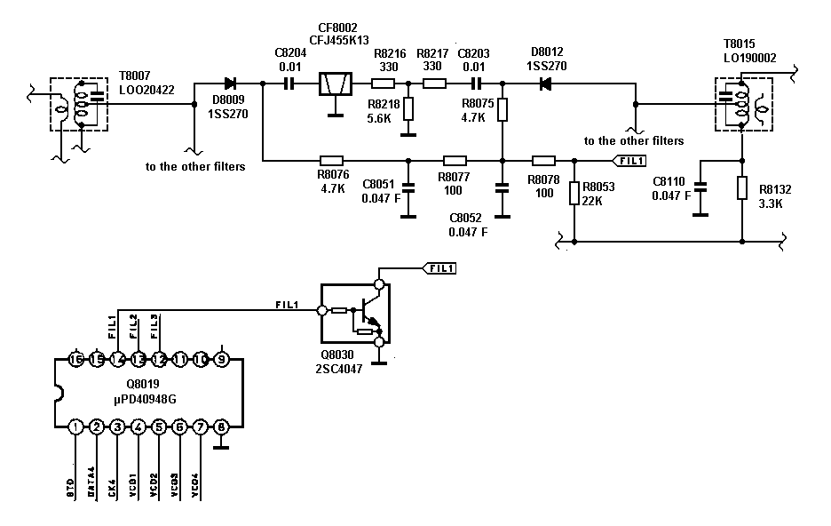
The circuitry around the CFJ455k13 looks like this:
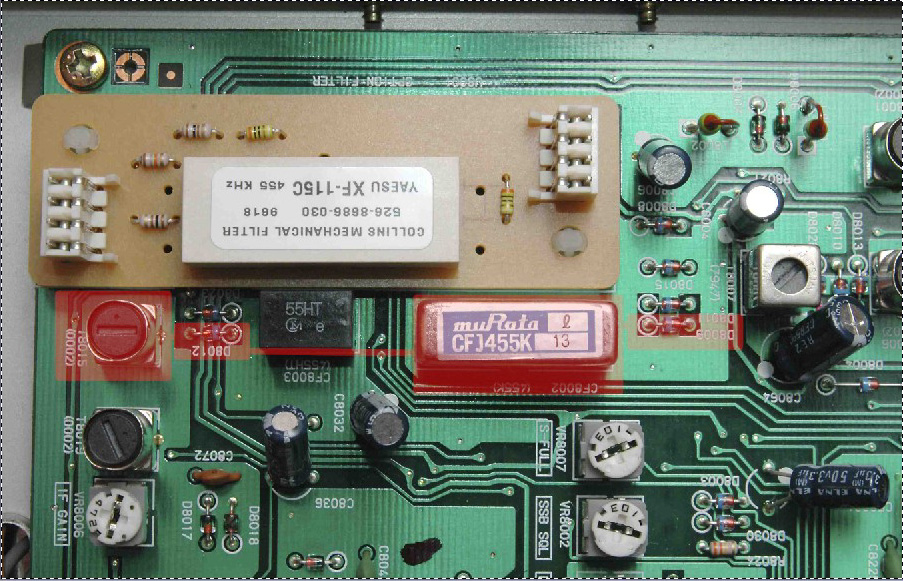
A photo showing the upper side of the PCB can be seen here. The key elements on the SSB path are shadowed by red. The auxuliary components are located on the bottom side. This schematics made me wonder why the T-circuit was placed behind the filter instead of in front of it?
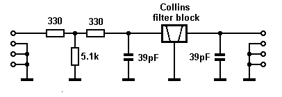
The schematics of the INRAD 720-C:
Seeing these the best idea would be to solder out the Murata ceramic filter and replace it with the Collins block. R8218 (5.6k) should be replaced to compensate the somewhat higher insertion loss of the narrower Collins crystal filter. The capacitors on the crystal filter should be kept and there is enough room for them on the bottom of the PCB
To-do-list:
Both the Sub VFO and the main VFO can be optionally equipped with a Rockwell Collins mechanical type filter. That is type XF-115C at Yaesu and 526-8686-030 at Collins.
This is a 500 Hz bandwidth, 7-pole mechanical filter for 455 kHz with 2000 ohms impedance. Collins informed me that it is nearly identical to their 526-8686-010 model with somewhat higher passband ripple. The datasheet of the latter type can be seen here.
An other option would be INRAD's 703C (400 Hz).
To-do-list:
This measurement is more for academic interest.
![]()